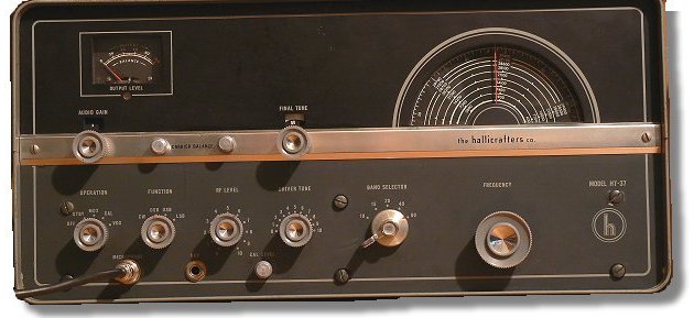
Hallicrafters HT-37
Audio Mods
Streamlined for "having been there done
that!"
1. Remove all knobs. (use Bristol wrenches for set screws).
2. Remove the top half cabinet, and the 5R4GY rectifier tube.
3. Turn the transmitter over and remove the bottom half cabinet.
4. The sideband generator unit sub chassis has 2 cinch plugs and a ground lug to microphone jack..remove both plugs from the sub chassis and unscrew the ground lug.
5. Turn the unit back upright.
6. Loosen the audio gain and plate control verniers on their respective shafts (with Bristol wrenches).
7. Remove the 6 front panel screws, and gently pull the panel off just enough to clear the knob shafts. (use something to lean it against).
8. Pull the microphone input (on sub chassis), and 9 MHz (to main chassis) RCA jacks out.
9. Remove the four screws surrounding the sideband generator to the chassis.
10. Pull the sideband chassis out with the back end angled up slightly.
11. Unscrew the cover from the sideband unit, and study the schematics below:
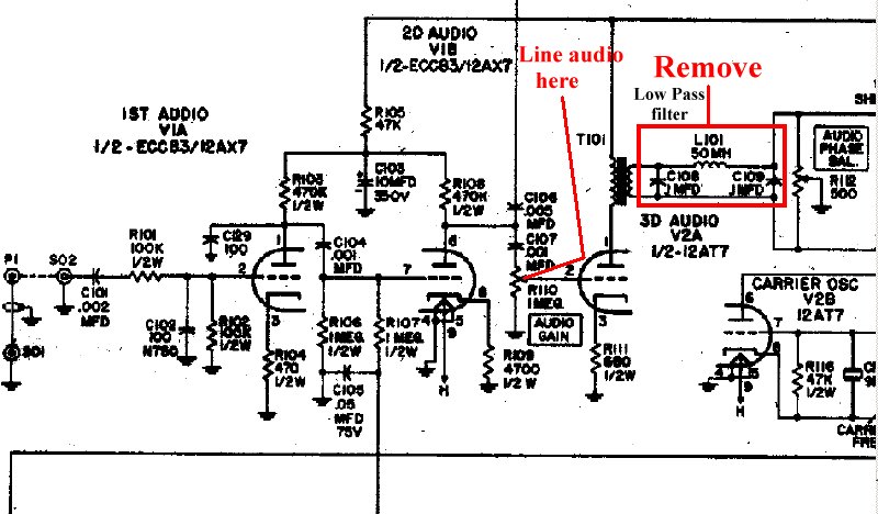
12. Snake a thin shielded audio cable through the front of the sideband generator chassis (you're now holding in your hands) so that it ends up near the audio gain shaft. Connect center conductor to the top of the 1 meg audio gain pot which leads to the grid of V2A (12AT7), and shield to ground side of the pot. Solder on a female RCA jack on the cable end coming through the chassis and tie wrap it onto the audio gain shaft sleeve so that it is physically near the female RCA jack on the chassis.
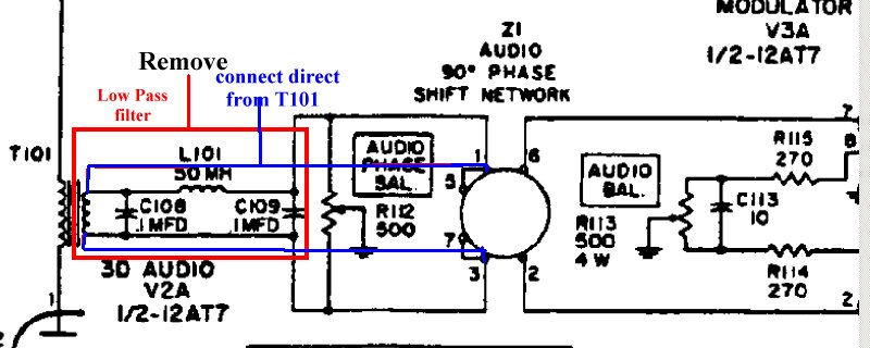
13. Time to remove the low pass nightmare in the audio path.. Directly below the phasing network, attached to unused lugs on the socket is L101 (50 mH). Snip that out and throw it into your junk box. Remove the two (.1 uF) caps (C108, 109) but keep the wire leads attached to them intact. Use those leads to connect T101 directly to pins 1 and 3 of the phasing network. Also, while you've got the unit in hand, replace the old 10 uF electrolytic (C103), check resistor values, etc.
14. Button the sideband generator back up and reverse the removal procedure..(remember to reattach the cinch plugs and ground lug!)..
15. Goes without saying that even nice audio sounds crappy with 120 cycle hum, so change all old electrolytics in all supplies including bias.. Speaking of bias, (thanks to a suggestion from Chris W2JBL), string some Zeners across the bias pot to clamp the voltage at -49 volts. This mod is not absolutely necessary but makes things a lot more linear (especially on ssb)..
The RCA female connector (that you ran out through the chassis), can be fed with any line level mixer, audio chain, etc. You can plug the male end RCA into your female run and use the front panel mic jack as an input, or run an XLR to RCA pigtail out the back (as I did) to a balanced audio source.
In all cases of using line-in, remove the 12AX7, (V1A,B)..
For stock audio (minus the low pass filter), plug the 12AX7 back in, reattach the RCA plug to it's normal configuration and talk..
After a few tests, this forgotten HT-37 is capable of 130% positive modulation with VERY low distortion, and sweeps out from 45hz to 12K..
One last note--- Follow the alignment procedures for sideband suppression with the phasing method after this mod. And, if you decide to fall to the dark side and use this on sideband, WIDE is an understatement!! ALL bandwidth is up to you on the AF side, and sharp cut off would be highly recommended...
Have fun and "See you on the Radio"..
Jeff W2NBC